

close
Choose Your Site
Global
Social Media
Views: 0 Author: Site Editor Publish Time: 2026-09-24 Origin: Site


Selecting a High-Pressure Plunger Pump based solely on isolated maximum ratings often leads to chronic mechanical failure. Relying on superficial metrics compromises operator safety. It also destroys overall system efficiency. Procurement and engineering teams frequently over-spec pressure parameters. Alternatively, they under-spec flow rates. This common mistake causes disastrous motor overload and internal cavitation. Ultimately, it leads to inadequate application performance. Buying equipment without analyzing the entire fluid dynamics cycle wastes capital. We want to provide a strict engineering framework for balancing pressure and flow effectively. You will learn how to calculate true power requirements for your specific fluid transfer needs. We will also guide you through configuring essential system components. This guarantees reliable, compliant operation every single time.
The Power Constraint: Pressure and flow share an inverse relationship dictated by available Brake Horsepower (BHP); maximizing both simultaneously requires exponential increases in motor size and capital cost.
Application Dictates Specs: Surface preparation relies on pressure to break bonds, while flushing and cleaning rely on flow for debris removal.
System Synergy is Mandatory: A pump's flow and pressure capabilities are entirely dependent on exact nozzle sizing; mismatched nozzles will instantly artificially cap performance or trigger bypass valves.
RPM dictates Flow: Modifying pump RPM directly scales the flow rate, but exceeding manufacturer RPM limits accelerates packing and valve wear.
Operating a pump continuously at its maximum rated pressure and flow simultaneously causes severe problems. Doing this exceeds continuous duty cycle limits. Manufacturers often list absolute maximums for intermittent use only. You cannot push the equipment to these extremes around the clock. Sustained maximum operation degrades internal components rapidly. It guarantees early mechanical failure for your industrial plunger pump. Engineers should always design systems to operate at roughly 70 to 80 percent of published maximums. This conservative approach extends equipment life significantly.
Insufficient inlet flow destroys equipment fast. Demanding more output than your feed line allows creates a vacuum effect. This vacuum forms microscopic vapor bubbles inside the fluid chamber. When these bubbles collapse under pressure, they generate intense shockwaves. We call this destructive process cavitation. Cavitation violently pits ceramics. It obliterates brass or stainless steel manifolds entirely. Furthermore, inadequate flow prevents proper fluid cooling. Heat builds up quickly around the internal packings. The resulting thermal expansion shreds seals and causes catastrophic leaks.
Selecting a pressure rating far beyond your application requirements wastes capital. It also introduces unnecessary mechanical fatigue. Pushing extreme PSI places immense stress on the crankshaft assembly. Connecting rods bear much heavier loads than required. This excessive force accelerates premature packing wear rapidly. Furthermore, oversized pressure ratings demand massive power consumption. You burn more electricity or diesel fuel for zero added benefit. Match your pressure precisely to the task to avoid these compounding failures.
Cavitation Indicators: Listen for a distinct rattling noise similar to pumping gravel.
Thermal Overload: Watch for rapid discoloration of the manifold metal.
Fatigue Signs: Inspect connecting rods for micro-fractures during routine maintenance.
System design always starts with understanding actual power requirements. You must calculate Brake Horsepower (BHP) accurately. The standard BHP calculation relies on a simple, universal formula. Use this equation: HP = (GPM × PSI) / 1460. For metric applications, use kW = (LPM × Bar) / 511. This math shows the strict inverse relationship between pressure and flow. Increasing flow means you must drop pressure to maintain the same horsepower. You cannot increase both variables simultaneously without upgrading your motor size exponentially. We rely on this equation to prevent system stalling.
Theoretical calculations rarely match real-world environments perfectly. You must account for volumetric efficiency loss during system design. Most modern fluid systems experience a 3 to 5 percent efficiency drop. Fluid compressibility plays a major role in this reduction. Valve delay also contributes to slight flow reductions during each stroke cycle. Plungers must reverse direction rapidly. This mechanical action allows a tiny amount of fluid slip before valves close fully. Factor this efficiency loss into your initial engineering calculations. It prevents disappointing flow rates out in the field.
Selecting the correct electric motor or diesel engine requires caution. Never match the drive horsepower exactly to your theoretical BHP calculation. Always add a 10 to 15 percent power safety margin. This buffer prevents the motor from stalling during heavy startup conditions. Starting under a heavy hydraulic load spikes electrical current draw momentarily. A properly sized drive handles these spikes effortlessly. It ensures smooth operation across varying daily duty cycles.
Flow Rate (GPM) | Target Pressure (PSI) | Theoretical BHP | Recommended Motor Size (HP) |
|---|---|---|---|
5.0 | 3,000 | 10.3 | 12.0 (or 15.0) |
10.0 | 5,000 | 34.2 | 40.0 |
20.0 | 10,000 | 137.0 | 150.0 - 160.0 |
50.0 | 2,000 | 68.5 | 75.0 - 80.0 |
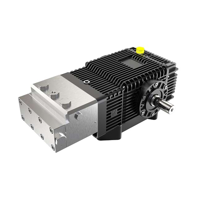
Engineers must configure systems based strictly on specific industry tasks. Coating removal and concrete scarification require immense concentrated force. Tube cleaning also demands high-impact kinetic energy. These specialized jobs typically require 10,000 to 40,000 PSI. Sometimes they require even more. A hydro blasting pump excels in these extreme environments.
The matching logic focuses intensely on pressure maximization. High PSI fractures tough surface bonds effectively. You only need a low-to-medium flow rate here. Maintain just enough flow to carry away the resulting debris safely. Pushing excess water during surface preparation creates unnecessary mess. It also wastes valuable pumping energy. Focus entirely on the concentrated kinetic energy of the water jet.
Assess the hardness of the material you need to remove.
Select a pressure rating capable of fracturing that specific material.
Determine the minimum flow required to wash away the fractured particulate.
Calculate the required engine size using the BHP formula.
Other applications prioritize volume over absolute fluid pressure. Mining equipment washdown relies on heavy bulk water movement. Sewer jetting and chemical injection also fall into this high-volume category. These tasks require moving heavy sludge rapidly. They also involve filling large-volume process pipelines quickly. High pressure alone fails completely in these scenarios.
The matching logic shifts entirely toward high volumetric impact (GPM). You need massive water flow to flush heavy debris physically. Keep your PSI only high enough to overcome system back-pressure. High pressure cannot compensate for inadequate flow when flushing large pipes. Choose a configuration delivering maximum gallons per minute for these specific chores. Flow is the primary cleaning agent here.
Flow rates tie directly to internal crankshaft speed. Modifying your pump RPM scales the flow rate mathematically. Reducing RPM by 20 percent reduces output flow by exactly 20 percent. However, your maximum pressure capacity remains completely unchanged. This strict linear proportionality makes system adjustments straightforward. A triplex plunger pump delivers consistent displacement per revolution. You can use pulley ratios to dial in the exact GPM. Variable frequency drives also provide excellent flow control. Just remember never to exceed the stated manufacturer RPM limits.
Water flows easily through internal pump valves. Thicker fluids require entirely different mechanical design considerations. Pumping highly viscous fluids demands significantly reduced operating speeds. Valves need more time to open and seat properly. Thick fluids naturally resist rapid directional changes inside the manifold. If you run viscous fluids at high RPM, the valves will float. This floating action destroys volumetric efficiency immediately. Consequently, pumping thicker fluids lowers your maximum achievable flow rate heavily.
Fluid temperature alters system dynamics drastically. High-temperature liquids increase your risk of cavitation substantially. Hot water turns into vapor much faster than cold water under vacuum conditions. You must boost your inlet feed pressure when handling hot fluids. A pressurized feed line forces the hot liquid into the cylinders forcefully. This prevents vapor bubbles from forming during the rapid intake stroke. Always install a booster feed pump for high-temperature applications. It protects expensive internal components from explosive cavitation damage.
Pumps do not create pressure inherently. They only produce consistent flow. The nozzle restriction creates the actual pressure in your system. This is a critical engineering distinction for system builders. If you use a massive nozzle, pressure remains low despite high flow. You must use a standard nozzle chart for accurate physical sizing. Match your exact GPM at the target PSI to find the correct orifice size. The overall performance of your high-pressure water pump depends entirely on this tiny component.
Fluid experiences severe friction as it travels through hoses. This friction causes a highly measurable pressure drop. Long hose runs compound this hydraulic energy loss significantly. A pump must output higher pressure at the manifold to compensate fully. This ensures you achieve your specific target pressure at the end-point tool. Calculate this frictional loss before finalizing your total power requirements. Increase your manifold PSI setpoint accordingly. Do not let friction rob your tool of necessary impact force.
System safety requires mandatory bypass mechanisms. You must include primary unloader valves in every single design. These devices divert flow safely when a trigger gun closes. You also need secondary pop-off or safety relief valves. Size these components specifically for the maximum GPM of the entire system. If a sudden blockage occurs, these valves prevent catastrophic pipe ruptures. They protect the operators and the machinery simultaneously. Never skip secondary safety relief valves to save a few dollars.
Selecting the perfect equipment requires following a strict decision tree. First, define your application target pressure and flow accurately. Second, calculate the required BHP using the standard engineering formula. Third, verify fluid compatibility regarding both viscosity and temperature. Finally, size the nozzle and bypass system to match your exact flow. Following this logic eliminates dangerous operational guesswork. It guarantees your mechanical components work in perfect harmony.
Proper system design prevents costly downtime and dangerous equipment failures. We strongly recommend seeking expert guidance for complex fluid transfer projects. Consult with an experienced applications engineer before finalizing your purchase. Bring your specific GPM, PSI, and fluid type data to the discussion. They will help you finalize the most efficient drive and manifold selection. Do not leave your operational success to chance.
A: No. The pump's flow is fixed by its internal displacement and operating RPM. A larger nozzle will only decrease the operating pressure. It will not increase the pump's GPM output whatsoever.
A: The pump will cavitate violently. This leads to severe mechanical vibration and immediate pressure loss. It also causes rapid destruction of the internal fluid end components, particularly the ceramics and seals.
A: No. Plunger pumps rely entirely on the pumped fluid to lubricate and cool the packings. Running dry, even for a few seconds, will cause critical seal failure and extreme heat buildup.
A: Pressure is controlled primarily by changing the nozzle size at the tool. You can also adjust the unloader valve to bypass excess flow. Alternatively, utilizing a variable frequency drive (VFD) alters motor speed and flow.


