

close
Choose Your Site
Global
Social Media
Views: 0 Author: Site Editor Publish Time: 2026-09-30 Origin: Site


Selecting the right equipment involves more than chasing maximum theoretical specifications. It requires matching strict operational limits to your actual commercial environment. Underspecifying equipment invites premature seal failure. It causes severe cavitation and creates frustrating project delays on critical job sites. Conversely, overspecifying leads to wasted energy and excessive strain on support systems. You need a setup built for your specific field reality.
This article provides a strictly technical framework. We will help you evaluate pressure, flow, and duty cycle requirements for demanding industrial applications. You will learn how to balance hydraulic limits against harsh environmental factors. We will guide you through specifying a system capable of surviving extreme conditions consistently. By understanding these mechanical boundaries, you can deploy equipment that runs reliably shift after shift.
Pressure vs. Flow: High pressure (PSI/bar) determines the ability to break chemical bonds (e.g., surface prep), while flow (GPM/LPM) dictates the clearing rate of debris.
Duty Cycle Reality: A true 100% continuous duty cycle requires specific RPM derating and enhanced thermal management; not all pumps labeled "heavy-duty" support 24/7 operation.
Material Compatibility: Manifold and plunger materials must align directly with the fluid’s temperature, corrosiveness, and abrasive particulate content.
Total Cost of Ownership: Upfront cost is secondary to the accessibility of wear parts (packings, valves) and the required maintenance intervals.
Mismatched pump specifications directly trigger severe contract overruns. They cause excessive downtime during critical operational phases. When a system lacks the necessary hydraulic horsepower, operators spend twice as long completing simple tasks. We do not define success merely by peak performance on day one. We measure success by consistent, reliable output across the entire scheduled maintenance interval. Equipment must perform predictably every single day.
Every individual component must work together seamlessly. The pump represents only one piece of a much larger puzzle. Unloader valves and safety nozzles must mathematically align with the system output. If nozzles are too small, they cause dangerous pressure spikes. If bypass valves are undersized, they generate excessive heat rapidly. The chosen drive type must match the hydraulic horsepower demands precisely. Whether you use an electric motor or a diesel engine, the power source dictates overall capabilities.
An improperly matched industrial cleaning pump disrupts this vital synergy immediately. This misalignment leads to premature wear on internal bearings. It eventually results in catastrophic system failure. Operators must view the entire skid as a unified ecosystem. Every valve, hose, and fitting must support the pump's specific operational limits.
Balancing pressure and flow requires understanding a fundamental inverse relationship. You face a fixed horsepower limit on any given machine. You cannot maximize both pressure and flow simultaneously without upgrading your primary power source. Choosing the right specifications dictates your daily operational efficiency. You must prioritize one metric based on your specific application.
A dedicated hydro blasting pump demands ultra-high pressure ratings. Applications like tube bundle cleaning and heavy scale removal often require 10,000 to 40,000 PSI. Concrete demolition also relies on this extreme force. This immense pressure physically shatters molecular bonds between hardened materials. It cuts through tough deposits without requiring massive volumes of water.
In contrast, a surface preparation pump requires a delicate, calculated balance. Tasks like paint removal or rust eradication need enough pressure to strip surfaces bare. However, they also demand sufficient flow to carry away the blasted material immediately. If your flow remains too low, debris simply re-adheres to the substrate. This forces operators to clean the exact same area twice.
General washdown and pipe jetting flip this equation completely. These specific applications rely on high-flow, moderate-pressure setups. Flushing large volumes of heavy debris requires moving massive amounts of water quickly. Municipal sewer clearing relies heavily on flow rate rather than cutting pressure. The sheer volume of water acts as a broom to sweep away loose obstructions.
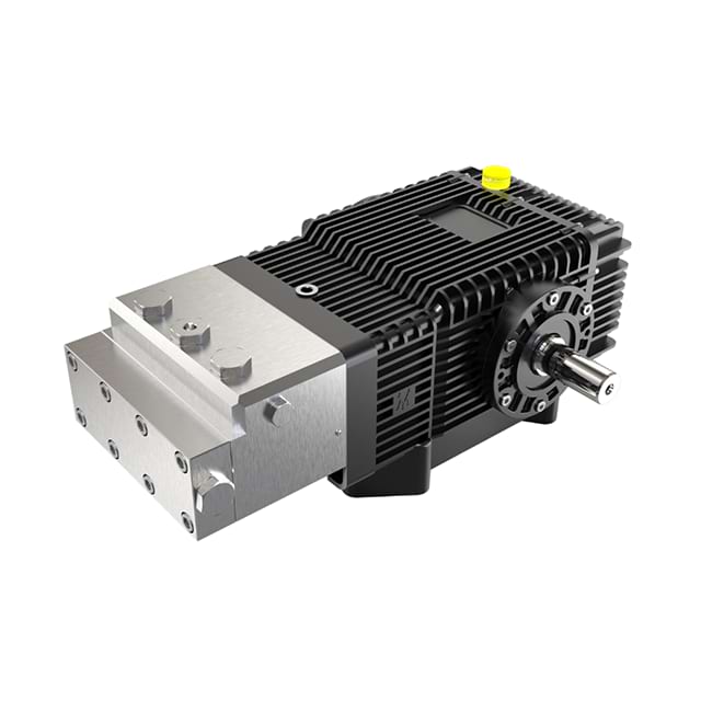
Many operators severely misunderstand pump duty cycles. This knowledge gap leads directly to catastrophic equipment failure in the field. Most standard high-pressure systems handle intermittent duty only. Manufacturers rate them safely for four to six hours of daily use. They require mandatory cooling periods between heavy trigger pulls. Pushing an intermittent-rated unit beyond these limits destroys internal seals rapidly. It also warps brass manifolds and degrades lubricating oil.
Achieving a true 24/7 continuous operation threshold demands specific mechanical adjustments. You must run these heavy-duty pumps at significantly reduced RPMs. Operating them at 50% to 60% of their maximum rated speed minimizes internal friction. For example, operators often use gearboxes to reduce a 1750 RPM drive down to 900 RPM. This massive reduction in operating speed drastically limits heat generation. It extends component life exponentially during continuous industrial processes.
Thermal dynamics play a critical role in system longevity. Crankcase oil capacity directly affects ambient heat dissipation rates. Larger oil reservoirs keep internal bearings cooler during extended runs. Cooling jackets help regulate internal temperatures during heavy industrial usage. Ambient operational temperatures also heavily impact the true duty cycle. Operating in a harsh, 100°F environment changes the thermal equation entirely compared to freezing conditions. Ignoring these thermal realities guarantees a shortened lifespan for your equipment.
Manifold construction sets the absolute operational limits of your system. Forged brass serves as the standard for commercial applications involving clean, fresh water. Aluminum bronze resists harsh corrosion effectively. This makes it ideal for environments utilizing brackish or salty water sources. Duplex stainless steel handles aggressive chemicals effortlessly. It offers extreme longevity under punishing industrial conditions.
Plunger technology also heavily dictates long-term durability. Solid ceramic plungers represent the undisputed industry standard today. They provide superior wear resistance against microscopic abrasives. They offer incredible thermal stability against constant friction. Unlike older metal alternatives, ceramic resists scoring entirely. This pristine surface extends packing life significantly. However, ceramic remains brittle and vulnerable to severe thermal shock.
Selecting the right seals requires evaluating fluid temperature and chemical exposure. Buna-N works exceptionally well for standard cold-water applications. Teflon handles harsh chemical solvents but lacks necessary physical elasticity. Viton provides excellent resistance to elevated temperatures and specific petroleum-based fluids. You must match the V-packing material to your exact fluid profile to prevent leaks.
Pumping high-temperature fluids carries massive implementation risks. Fluids exceeding 140°F (60°C) cause standard elastomer materials to degrade instantly. The heat softens the packings, leading to immediate pressure loss. You must utilize specialized high-temp seal kits for these applications. These upgraded kits prevent catastrophic blowout during thermal expansion.
Fluid Compatibility and Material Guide
Fluid Type | Recommended Manifold | Preferred Seal Material | Temperature Limit |
|---|---|---|---|
Standard Tap Water | Forged Brass | Buna-N | Up to 140°F |
Brackish/Salt Water | Aluminum Bronze | Buna-N / Viton | Up to 140°F |
Harsh Chemicals | Duplex Stainless Steel | Teflon | Chemical Dependent |
High-Temp Washdown | Stainless Steel | Viton / High-Temp Kits | Up to 180°F+ |
We must approach wear analysis strictly through an evidence-oriented lens. Valves, packings, and plungers will inevitably wear out during normal operation. You must evaluate pumps based on how easily you can service these fluid-end components. Complex teardowns waste valuable operational hours. They frustrate maintenance teams working in harsh field conditions. Easy access to valve caps and packing cylinders remains absolutely crucial for daily efficiency.
Cavitation remains the absolute leading cause of premature failure. This destructive phenomenon occurs when a starved suction line creates vacuum bubbles. These microscopic bubbles violently implode against internal metal parts. They pit the manifold and destroy plungers rapidly. Preventing cavitation requires flawless inlet plumbing design. You must maintain adequate feed pressure at all times. You must also utilize high-capacity, fine-micron filtration to protect the entire system.
Equipment downtime derails project timelines entirely. Frame your initial equipment choices against the sheer availability of replacement parts. Rebuild kits must remain accessible on incredibly short notice. A manufacturer's technical support infrastructure proves invaluable when troubleshooting complex hydraulic failures. Waiting weeks for specialized replacement valves halts industrial operations. You should always choose platforms supported by robust, local parts inventories.
Selecting the ideal High-Pressure Plunger Pump follows a precise, mathematical sequence. Use these exact steps to build a highly reliable specification framework for your facility.
Step 1: Define the Required Hydraulic Output. Calculate the exact PSI and GPM needed at the nozzle. You must factor in severe pressure drops occurring over long hose runs.
Step 2: Determine Operational Hours. Categorize your daily usage accurately. Decide if you need light-commercial, heavy-intermittent, or true continuous industrial capabilities.
Step 3: Select the Drive and RPM. Direct drive systems offer highly compact footprints. However, they run at higher RPMs, which increases friction and wear. Belt or gearbox drives operate at much lower RPMs. This mechanical advantage ensures longer life despite their bulkier size.
Step 4: Consult Application Engineers. Direct your specific requirements to technical experts immediately. They will help finalize pump configuration, unloader selection, and critical safety relief mechanisms.
Before finalizing any order, ensure every component of your high-pressure water pump integrates flawlessly.
Specifying an industrial cleaning pump requires a highly holistic view. You must balance pressure, flow, and structural durability equally. Verifiable reliability and maintenance accessibility always outweigh theoretical maximum specifications. Field performance matters far more than peak laboratory numbers. Systems must survive real-world abuse consistently.
To ensure lasting success, take the following action-oriented next steps:
Audit your existing water supply for maximum flow rate and abrasive particulate levels.
Document your exact daily operational hours to determine true duty cycle needs.
Map out your required hose lengths to calculate exact pressure drop metrics accurately.
Submit your required flow, pressure, and application details to a qualified engineering team.
Request a custom engineering review and quote today to build a system engineered for rugged survival.
A: Plungers move past stationary seals, which allows for much higher pressure capabilities. Pistons carry the seal with them as they move along the cylinder wall. This dynamic movement limits piston pumps to lower pressure applications due to significantly increased seal wear and friction.
A: No. Running dry causes immediate and severe friction heat. This extreme heat will melt internal packings and crack ceramic plungers within minutes. You should always use low-water shutdown sensors to protect your equipment from accidental dry runs.
A: Use the standard industry formula: (GPM x PSI) / 1460 = Electric Motor HP. You should then add a standard 15% to 20% buffer. This buffer accounts for mechanical efficiency losses and ensures the motor is not constantly overworked during operation.


