

close
Choose Your Site
Global
Social Media
Views: 0 Author: Site Editor Publish Time: 2026-10-07 Origin: Site


Procurement stakes are remarkably high when specifying heavy-duty fluid handling equipment. Selecting the wrong pump specifications routinely leads to premature seal failure. System downtime escalates quickly in these scenarios. Blown operational budgets soon follow. Catalog specifications often look deceptively simple on paper. Basic performance metrics like PSI and GPM rarely tell the whole story. Real-world application variables dictate true operational success. You must account for dynamic fluid temperatures and strict duty cycles. Inlet plumbing conditions also play a massive role in hardware longevity. This guide establishes an evidence-based, engineering-focused tone for evaluating equipment. We will explore critical mechanical specifications thoroughly. You will learn how to match core performance metrics before placing an order. We will also examine material compatibility and crucial system integration requirements. Proper specification ensures your system runs efficiently for years without catastrophic failure.
Matching Pressure (PSI/Bar) and Flow (GPM/LPM) to exact application requirements prevents energy waste and system bypass wear.
Manifold and seal material compatibility must be dictated by the specific fluid being pumped (e.g., abrasives, extreme temperatures, corrosive chemicals).
Ordering a continuous-duty pump requires evaluating operating RPM; lower RPM generally extends packing and valve life.
Establishing the correct baseline for your pumping system begins with understanding horsepower limits. A fundamental inverse relationship exists between flow rate (Gallons Per Minute or GPM) and pressure (Pounds Per Square Inch or PSI). If your available motor horsepower remains constant, increasing the system pressure naturally decreases the maximum achievable flow rate. Engineers use a standard industry calculation to determine this balance. You multiply GPM by PSI, then divide by a constant of 1460 to find the required Electric Brake Horsepower. Getting this baseline right prevents severe mechanical overloading.
Many operators fall into the trap of over-speccing their equipment. They assume bigger is always better. Ordering a pump with significantly higher pressure capabilities than necessary introduces immediate risks. Excess pressure often forces the unloader valve into continuous bypass mode. When a pump bypasses too much fluid, it generates tremendous internal heat. This heat degrades seals rapidly. Furthermore, running an oversized system wastes substantial electrical or fuel energy. You end up paying for performance you never actually use.
Operating speed directly impacts the mechanical wear of your equipment. A distinct tradeoff exists between pump speed and overall longevity. Every revolution of the crankshaft causes the plungers to stroke, creating friction against the stationary seals. When you operate an industrial plunger pump at a lower RPM, you significantly reduce cycle fatigue. Savvy engineers often oversize the pump slightly in terms of maximum flow capacity. They then under-drive it using pulleys or gearboxes. This lower rotational speed reduces internal heat generation. It ultimately extends the life of both the packing seals and the check valves.
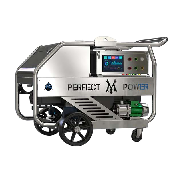
Selecting the right metallurgy for your pump head determines its survival in harsh environments. The manifold is the primary block where fluid compression occurs. Standard brass manifolds work perfectly for everyday applications. Most standard commercial washing systems rely on brass because it handles fresh water and mild detergents effectively. However, brass fails quickly when exposed to harsh environments.
More demanding applications require advanced metallurgy. If you pump saltwater, harsh chemicals, or deionized water, standard brass will suffer from rapid corrosion or dezincification. In these scenarios, you must specify Nickel Aluminum Bronze or Stainless Steel (304/316 grades). Stainless steel is practically mandatory for reverse osmosis systems and corrosive chemical injection.
Pump Head Material Comparison
Manifold Material | Ideal Application | Common Limitations |
|---|---|---|
Forged Brass | Standard fresh water, mild detergents | Susceptible to dezincification in saltwater |
Nickel Aluminum Bronze | Brackish water, seawater desalination | Higher upfront cost, heavier footprint |
316 Stainless Steel | Reverse osmosis, harsh chemicals | Can suffer from galling without proper maintenance |
Plunger material selection is equally critical for a reliable high-pressure water pump. Most modern designs utilize solid ceramic plungers. Solid ceramic offers exceptional wear resistance and handles abrasive particulate better than standard metals. However, solid ceramic can crack under extreme thermal shock. If your application involves rapid temperature swings, you might need ceramic-coated plungers or specialized solid metal plungers to prevent shattering.
You must also scrutinize your seal and packing formulations. The standard elastomers installed at the factory may melt or dissolve if exposed to aggressive fluids. Always shortlist your seals based on chemical aggressiveness and fluid temperature:
Buna-N (Nitrile): The industry standard for cold to warm fresh water. Excellent resistance to standard petroleum-based oils.
FPM (Fluorocarbon/Viton): Essential for high-temperature fluids and aggressive chemical blends. It resists degradation from harsh solvents.
EPDM (Ethylene Propylene Diene Monomer): Required when pumping specific alkaline fluids or automotive brake fluids. Never use EPDM with petroleum products.
You must rigorously define your intended duty cycle before placing an order. Intermittent operation characterizes systems like manual car washes or occasional pressure washing tasks. These systems might run for only an hour or two per day. They allow the pump block and crankcase oil to cool down completely between uses. Conversely, industrial applications demand a completely different engineering approach.
Specifying a true continuous-duty pump requires planning for 24/7 operation. When a pump runs without stopping, thermal management becomes your biggest obstacle. Continuous friction heats the crankcase oil. If the oil gets too hot, it loses its lubricity, leading to catastrophic bearing failure. Heavy-duty applications often require larger crankcase oil capacities. Some continuous setups even mandate active external cooling loops to keep oil temperatures within safe operating thresholds.
Drive integration dictates how power transfers from the motor to the pump. Direct drive systems connect the motor directly to the pump shaft. This method is compact but forces the pump to run at the exact speed of the motor. V-belt drives offer tremendous flexibility. They allow you to alter the pulley ratios, reducing the pump RPM for continuous duty. However, V-belts introduce side-load tension on the pump shaft bearings. Gearbox drives provide a middle ground. They reduce motor RPM efficiently without placing side-load stress on the bearings. Your drive choice dictates the required shaft size and orientation specification.
Proper system integration begins at the fluid source. Cavitation is the silent killer of pumping equipment. Cavitation occurs when the pump demands more fluid than the inlet plumbing can supply. The resulting pressure drop causes the fluid to vaporize momentarily. These vapor bubbles then implode violently inside the manifold, blasting away the metal. Evaluating a hydraulic plunger pump requires carefully calculating the Net Positive Suction Head (NPSH). You must ensure the available suction head (NPSHa) always exceeds the required suction head (NPSHr) dictated by the manufacturer. You prevent starvation by using oversized inlet hoses, minimizing elbows, and avoiding long suction runs.
A bare pump is essentially a raw compression mechanism. It cannot operate safely without specific system accessories. Positive displacement pumps move a fixed volume of fluid with every stroke, regardless of downstream blockages. If you dead-head the system without proper regulation, the pressure will spike until the manifold cracks or a hose explodes. You must integrate specific safety and regulation accessories:
Unloader Valves: These divert fluid into a bypass loop when the downstream trigger is released. They prevent pressure spikes and keep the motor running safely.
Pressure Relief Valves: This is a mandatory fail-safe. If the unloader valve jams, the relief valve pops open at a predetermined pressure, dumping water to the atmosphere to prevent an explosion.
Pulsation Dampeners: Plunger pumps inherently create pressure spikes with every stroke. Dampeners absorb this kinetic energy, smoothing the flow and protecting downstream gauges and pipes.
Finally, tight-tolerance valves demand exceptional filtration. Abrasive particulate acts like liquid sandpaper inside the manifold. It scores the ceramic plungers and ruins the high-pressure packing seals. You must detail specific micron filtration requirements based on your water source. Pumping reclaimed water or well water usually requires stepping down through multiple filters, terminating in a 10-micron or 50-micron filter immediately before the inlet port.
Successful equipment specification always requires looking past the bold catalog numbers. Moving beyond top-line pressure ratings allows you to analyze actual fluid dynamics and environmental conditions. You must prioritize fluid compatibility, precise duty cycles, and strict thermal management. The surrounding system architecture matters just as much as the primary pump block. Poor inlet plumbing or inadequate filtration will destroy even the highest-quality metallurgy.
Before requesting a final quote or placing an order, compile a comprehensive application datasheet. Document your exact fluid type, peak operating temperature, and continuous duty hours. Detail your available inlet conditions and preferred drive mechanics. Sharing this granular data with your distributor ensures they configure a highly optimized High-Pressure Plunger Pump. Taking these steps guarantees a resilient, efficient system built for long-term operational success.
A: The primary difference lies in the sealing mechanism. In a plunger pump, the packing seals remain stationary inside the manifold, and a smooth ceramic plunger moves back and forth through them. This design handles significantly higher pressure limits. In a piston pump, the seal is attached directly to the moving piston and travels with it along the cylinder wall. Piston pumps are generally limited to lower pressure applications.
A: No. Running dry causes catastrophic friction immediately. The fluid being pumped acts as the primary lubricant and coolant for the packing seals. Without fluid, the internal seals will overheat, melt, and fail completely within minutes. Unless you specify highly specialized, custom-engineered run-dry packings, you must always guarantee an uninterrupted fluid supply before engaging the motor.
A: You can determine the required motor size using a standard industry formula. Multiply your desired flow rate (GPM) by your target pressure (PSI). Divide that total number by 1460. The result is the minimum Electric Brake Horsepower needed to drive the pump safely. Always factor in a slight buffer to prevent the electric motor from running continuously at its absolute maximum load.


