

close
Choose Your Site
Global
Social Media
Views: 0 Author: Site Editor Publish Time: 2026-10-03 Origin: Site


Unplanned pressure loss in fluid systems leads to immediate operational downtime. It compromises strict cleaning and processing standards across your facility. Ignoring these pressure drops often accelerates severe wear on related downstream equipment. Diagnosing a pressure drop requires systematically isolating the system rather than guessing at parts. A sudden loss in pressure is usually a distinct symptom of fluid starvation. It can also stem from hidden component wear or bypass system failures. We provide a technical diagnostic framework here. You will learn how to identify the exact root cause of pressure loss accurately. We will help you evaluate whether a targeted component rebuild or a complete pump replacement makes the most sense for your operation. This detailed guide empowers maintenance teams to restore critical fluid system integrity quickly and safely without wasting capital.
Sudden pressure drops typically indicate acute blockages (e.g., a jammed pump check valve) or external system failures (e.g., unloader bypass).
Gradual pressure degradation is almost always linked to abrasive wear on plunger pump seals or the nozzles.
Diagnostics must begin at the inlet supply; treating the pump before verifying adequate water flow leads to misdiagnosis and wasted capital.
The decision to repair versus replace hinges on the condition of the manifold and the ceramic plunger integrity, not just the consumable seals.
Operators often mistake an external system restriction for a true pump failure. This error leads to unnecessary teardowns and extended operational downtime. You must isolate the system first to distinguish between internal wear and external blockages. A systematic approach prevents maintenance teams from chasing the wrong variables.
You must establish what normal operation looks like before diagnosing a failure. Compare the current operating pressure and fluid flow against the system’s original design parameters. Find the manufacturer specifications for your specific unit. A baseline gives you a concrete reference point. Without this baseline, you might try to repair a pump performing exactly as designed.
Follow these best practices for baseline verification:
Record the original flow rate in Gallons Per Minute (GPM) or Liters Per Minute (LPM).
Document the maximum rated operating pressure.
Note the specific RPM rating of the drive motor.
Check the fluid temperature limits recommended by the manufacturer.
Visual inspections rarely reveal the true source of a pressure drop. You need accurate data. Install a diagnostic pressure gauge directly at the pump discharge head. You must bypass all downstream equipment to isolate the pump's true performance. Downstream equipment includes unloader valves, hoses, and spray guns.
If the gauge reads the target pressure at the discharge head, the pump operates correctly. The problem lies further down the line. If the gauge shows low pressure directly at the head, you have isolated the issue to the fluid supply or the pump itself. This simple test saves hours of frustrating labor.
Many operators confuse flow with pressure. A pump produces flow. Restrictions in the system produce pressure. The primary restriction is usually the discharge nozzle. If the flow remains constant but the pressure drops, the issue often sits downstream. A worn nozzle simply cannot hold back the fluid to build adequate pressure. Conversely, if both flow and pressure drop simultaneously, the pump likely suffers from internal wear or inlet starvation. Understanding this distinction forms the foundation of accurate troubleshooting.
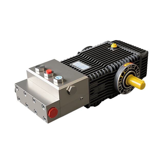
Most reported pump failures actually begin as starvation issues at the inlet. When a system cannot draw enough fluid, it experiences severe mechanical stress. You must verify adequate water flow before touching the actual pump hardware.
Fluid starvation leads directly to cavitation. Cavitation refers to the rapid formation and collapse of vapor bubbles inside the fluid stream. These bubbles form when the inlet pressure drops below the fluid's vapor pressure. When these bubbles enter the high-pressure chamber, they collapse violently. These collapsing bubbles act like tiny explosions. They tear away microscopic pieces of metal from the manifold.
A cavitating pump often sounds like it has gravel tumbling inside the crankcase. Ignoring this sound guarantees catastrophic internal damage. You must treat cavitation as an acute emergency.
You must inspect the entire supply line systematically. Begin at the water source and work your way to the inlet port.
Check for inadequate feed pressure: Measure the water pressure entering the system. Municipal water supplies often fluctuate. Ensure the supply line diameter matches the manufacturer's minimum requirements.
Inspect inlet strainers: Filtration systems catch debris before it enters the fluid end. However, a clogged strainer acts as a severe bottleneck. Clean or replace inlet strainers daily during heavy operations.
Identify air leaks: Suction lines often develop microscopic cracks. Loose hose clamps also invite trouble. These leaks introduce compressible air into the fluid stream. Air immediately kills output pressure because pumps move liquid, not gas.
Common Mistake: Many facilities upgrade their equipment for higher flow rates but forget to upgrade the inlet plumbing. Trying to pull 10 GPM through a hose designed for 5 GPM will always cause starvation.
Operating a High-Pressure Plunger Pump under cavitation conditions causes irreversible damage. The violent micro-explosions permanently pit internal brass or stainless steel manifolds. Furthermore, the immense vibration shatters fragile internal components. Always verify an adequate, clean, and air-free inlet supply before dismantling the fluid end. Proactive inlet maintenance protects your expensive capital equipment from premature destruction.
When you verify the inlet supply runs perfectly clear, shift your focus to the fluid end. This section contains the components responsible for trapping and moving the fluid. High friction, intense pressure, and harsh chemicals take a toll on these internal parts.
Seals keep the pressurized fluid contained within the manifold. They represent the most common wear item in any fluid system.
You will often notice water weeping from the space between the manifold and the crankcase. This visual cue indicates a compromised seal. You will also notice a gradual, steady reduction in working pressure. To evaluate the failure, assess the physical condition of the extracted seal.
Normal Wear: The seal looks evenly worn down. This happens naturally over hundreds of operational hours.
Thermal Shock: The seal appears melted or deformed. This happens when the system runs dry, generating extreme friction and heat.
Chemical Incompatibility: The seal looks swollen, brittle, or cracked. Harsh cleaning agents often destroy standard Buna-N or polyurethane materials.
Replacing plunger pump seals represents a routine maintenance task. However, you must identify why they failed to prevent rapid recurrence.
The check valves act as one-way doors. They allow fluid to enter the cylinder and force it out the discharge port. A functioning valve requires a perfect seal between the poppet and the seat.
If a valve fails, you will notice distinct symptoms. The high-pressure hose will exhibit a violent, rhythmic pulsation. You might experience a sudden, partial pressure drop. Erratic gauge readings also point directly to a valve issue.
To evaluate the situation, remove the valve caps and inspect the assemblies. Look closely at the o-rings and valve seats. A single piece of sand or scale preventing a valve from seating destroys the system's volumetric efficiency. Check the metal surfaces for scoring. High-velocity water squeezing past a stuck valve will quickly carve channels into the stainless steel seat. If you find deep scoring, you must replace the entire pump check valve assembly.
The plungers drive into the fluid chamber to create flow. Most industrial systems use ceramics because they resist wear and withstand harsh chemicals beautifully.
A damaged plunger often reveals itself through the premature failure of new seals. If you replace the packings and they leak again within a week, suspect the plunger. To evaluate it, remove the manifold and clean the plunger thoroughly. Run your bare fingernail horizontally over the ceramic surface. If your nail catches on any perceptible groove, the component is ruined. Thermal shock from sudden temperature changes also causes hairline cracks. A scored or cracked ceramic plunger acts like a file against the soft rubber seals. It cannot hold a high-pressure seal and requires immediate replacement.
The internal pump mechanism is only one half of the pressure equation. The rest of your system dictates the final output. Operators frequently blame the fluid end when the actual culprit sits downstream. You must perform a holistic system evaluation.
The discharge nozzle creates the restriction necessary to build pressure. It acts as the final gatekeeper for your fluid.
High-pressure water naturally enlarges nozzle orifices over time. Water erosion acts slowly but relentlessly. A larger orifice requires significantly more flow to maintain the same baseline pressure. If you verify the pump delivers its full rated flow, but the pressure remains low, check the nozzle. Replacing a worn nozzle often serves as the fastest, cheapest fix for a gradual pressure drop. Always keep perfectly sized spare nozzles in your maintenance kit for quick substitution testing.
The unloader valve dictates the maximum system pressure. It diverts excess fluid back to the inlet or the holding tank when you release the spray gun trigger. It serves a critical safety function.
If the internal bypass mechanism channels, problems arise immediately. High-velocity fluid carves microscopic grooves into the brass bypass seat. A fatigued internal spring also causes premature bypassing. When this happens, fluid escapes back to the inlet before it ever reaches the nozzle. This limits the maximum pressure the system can achieve.
Diagnostic Logic: Never arbitrarily tighten the unloader spring to compensate for low pressure. This masks the real problem. If you tighten it fully and still lack pressure, the unloader seat is likely washed out.
You must rule out mechanical power loss before tearing into fluid components. The system relies entirely on the rotational energy provided by the drive motor.
Slipping drive belts reduce the operating RPM. A failing electric motor or a bogging gas engine produces the same result. A lower RPM proportionately drops both the flow rate and the maximum pressure. Inspect belt tension regularly. Look for black rubber dust around the pulley guards, which indicates severe belt slip. Ensure pulleys are aligned properly. Use an optical tachometer to verify the actual RPM at the crankshaft matches the manufacturer specifications.
Once you identify the root cause, you face a critical operational decision. How do you determine the most capital-efficient path to restore operations? You must weigh the cost of parts and labor against the penalty of extended downtime.
Pump Maintenance Decision Matrix
Component Condition | Recommended Action | Labor Intensity | Expected Longevity |
|---|---|---|---|
Leaking seals, smooth ceramic plungers, intact manifold | Rebuild (Seal/Valve Kits) | Moderate (1-2 Hours) | High (Like New) |
Scored plungers, repeated seal failures | Replace Plungers & Seals | Moderate (2-3 Hours) | High (If root cause fixed) |
Pitted manifold from cavitation | Replace Fluid End | Low (Bolt-on Replacement) | Very High |
Milky crankcase oil, loud knocking noise | Upgrade Complete Pump Unit | Low (Swap entire unit) | Maximum (New Unit) |
Rebuilding makes the most sense for routine wear and tear. Choose this path when the brass or stainless steel manifold remains perfectly uncompromised. You must also verify the plungers feel completely smooth. Rebuilding utilizes low-cost consumable parts. However, it requires skilled maintenance labor and scheduled downtime. If your technicians lack experience, they might install the seals backward or pinch an o-ring. Train your team thoroughly before relying on in-house rebuilds.
You must replace hard components under specific extreme conditions. Do this if prolonged cavitation has pitted the internal fluid end chambers. You must also replace them if thermal shock has cracked a plunger. Conduct a strict risk assessment here. Re-packing a scored or cracked pump guarantees a repeat failure within weeks. The cost of a new plunger easily justifies the prevention of a secondary, unplanned shutdown.
Sometimes, repairing an old system wastes money. You should upgrade the complete high-pressure pump unit in several scenarios.
Catastrophic Failure: If the crankcase oil looks milky, high-pressure water has breached the oil seals. This destroys the internal bearings and the crankshaft. Repairing a flooded crankcase rarely succeeds long-term.
The 50% Rule: If the cost of a new manifold, replacement plungers, and maintenance labor exceeds 50% of the cost of a brand-new pump, replace it. A new unit carries a fresh warranty and guarantees reliability.
Scalability Considerations: Evaluate your current operational needs. If your facility now requires higher duty cycles or harsher chemicals than the existing unit was specified for, upgrade. Forcing an undersized unit to perform heavy-duty tasks ensures constant breakdowns.
Diagnosing pressure loss requires a strict, systematic approach. Always start your investigation at the water source to verify adequate supply. Check downstream restrictions like worn nozzles and faulty unloaders before you tear down the internal fluid end. Blindly replacing internal parts wastes both maintenance time and operational budget. We encourage operators to consult their equipment diagrams regularly. Secure OEM replacement kits to maintain system integrity safely. You can also contact a technical specialist to match a replacement pump exactly to your compliance and operational parameters. Proactive diagnostics and smart replacement strategies keep your critical fluid systems running efficiently year round.
A: Wild gauge fluctuations usually indicate cavitation or a stuck inlet check valve. Cavitation happens when the system starves for water, pulling air into the fluid stream. A piece of debris trapped in the check valve also prevents it from seating fully, causing the pressure to spike and drop rhythmically with every stroke.
A: No. Tightening the unloader valve to compensate for low pressure is a dangerous, non-compliant practice. It masks the real issue, which is usually a worn discharge nozzle or failing pump seals. Over-tightening creates dangerous pressure spikes when the trigger is released, potentially rupturing hoses or damaging the internal bypass mechanism.
A: Seal lifespan depends heavily on your specific application. Standard clean-water applications often see seals last 500 to 1,000 hours. However, harsh chemicals, high temperatures, or recycled water with abrasives can reduce this lifespan to 300 hours or less. Establish a preventative schedule based on your unique operational severity.


